Project setup
In the first six months of the project, we have established the internal procedures, governance, quality assurance etc. in BRAVA in the Project Handbook (LINK). As well the Data Management Plan (DMP) of BRAVA was presented (Deliverable D1.2), specifying which data will be generated in the project, the standards and methodology that will be used, how the data will be exploited and/or shared and made accessible for verification and re-use and how this data will be curated and preserved. (see for more info here). To support achieving the BRAVA objectives and reaching the set targets for key performance indicators thereof in terms of resources, quality and impact of BRAVA, the introduction of risk management procedures as well as the protocols related to the risk management and risk mitigation measures was established (LINK). In addition, the preliminary plan for dissemination and communication (link to D7.1) incl. the project’s brand identify was set to maximise the impact of the BRAVA Fuel Cell (FC) Power Generation System (PGS) subsystems and promote its future widespread use in aviation and possibly in other branches of transport.
Technical activities – from aircraft requirements to PGS
But more interestingly, the technical activities for BRAVA in these first six months were heavily related to the setting of the requirements cascading from the high level aircraft product target requirements (100 passengers, range 1,000 nautical miles and flying at 25,000 ft), with more information in the executive summary of D2.1 PGS system architecture and requirements to cascade down to the PGS level to provide 2.2 MW per unit and further to the subsystem levels of air supply, stack and cooling system.
Requirements for thermal management system
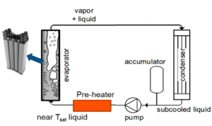
In “D2.2 2-PC and AM requirements”, these requirements are used to specify the requirements for the three different systems of the Thermal Management System (TMS) that are developed in BRAVA’s WP3 (see D2.2 2-PC and AM requirements executive public summary for more information). From the stack requirements (see below) and the TMS requirements the requirements for a two-phase cooling (2-PC) system that is going to be used for cooling a fuel cell (FC) prototype within the project of BRAVA were set, with more details in D3.1 FC requirements for a 2-PC system and an explanatory figure on a classical two-phase system with the evaporator in this case being a fuel cell stack (with photo EKPO NM12 from https://www.ekpo-fuelcell.com/en/products-technology/fuel-cell-stacks)

Heat exchangers (HEX) from the TMS within this high performing PGS need to dissipate up to 1 MW of heat while being compact, lightweight and corrosion resistant, considering the environmental conditions to which they are subjected. AM technology brings design flexibility and integration as the main advantages (see the summary of D3.2 AM HX requirements and KPIs for more information).
Stack requirements
The stack requirements were derived from the top level requirements stated in D2.1 Deliverable “PGS system architecture and high level requirements on PGS level and the sub-system requirements as stated in “D2.3 Stack component requirements” public summary.
Air Supply system requirements
Following product level and sub-systems requirements definition, and an architecture trade-off, D2.4 Air Supply system requirements defined the Air Supply Product architecture and a first step of Air Supply Product requirements (see D2.4 Air Supply system requirements executive public summary for more information). Based on given requirements from deliverable 2.4 , several trade studies were performed to improve the overall system performance (D5.1 Report on system architecture).

